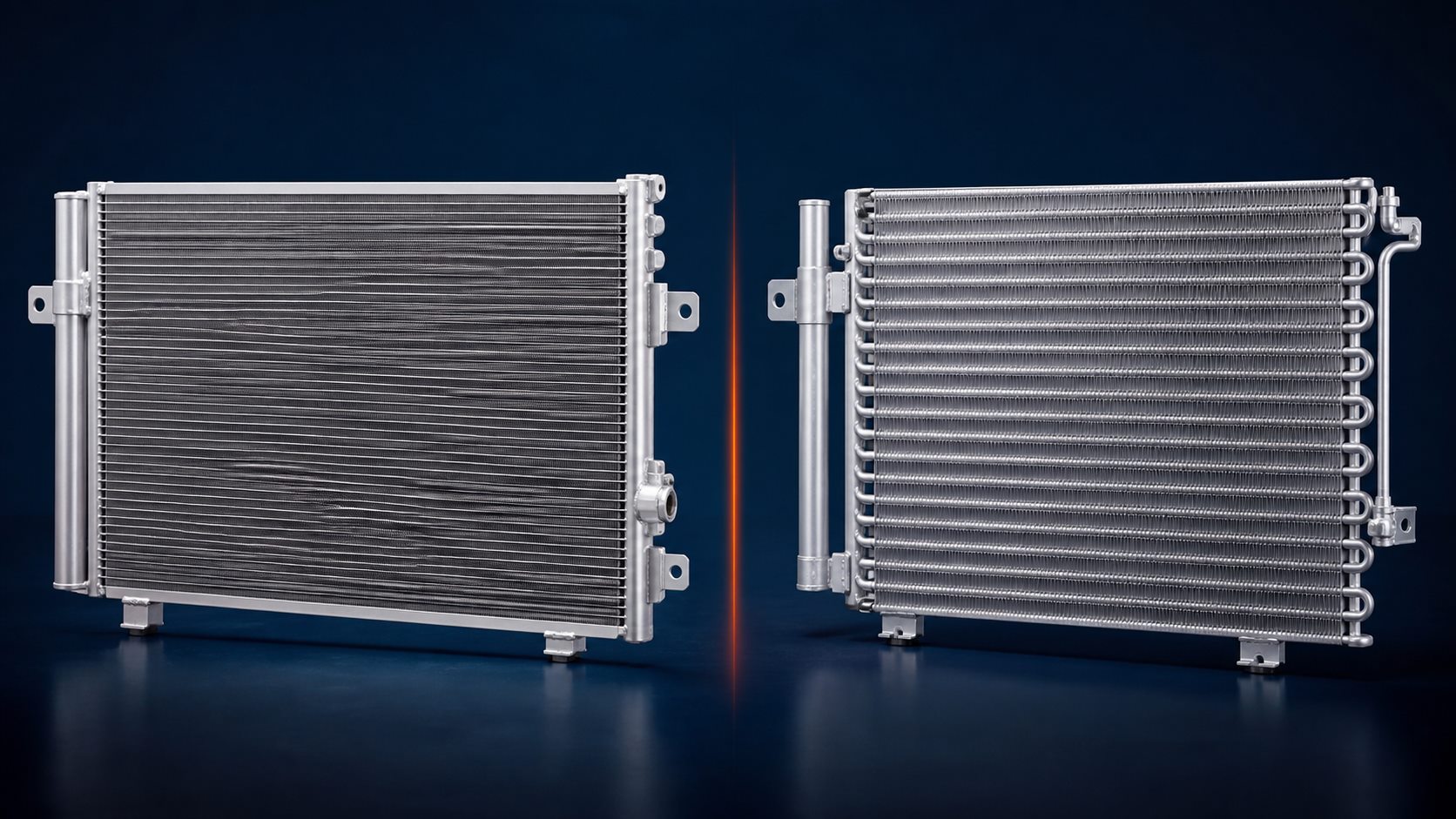
Serpentine construction
A serpentine condenser normally uses a continuous tube that travels back and forth through the fin pack. Refrigerant follows one extended route through multiple passes, and return bends are often visible along one side.
This construction appears in many earlier vehicle applications. Identification must still include the connections, mountings, core size, and vehicle application because appearance alone is not an approval method.
Parallel-flow construction
A parallel-flow condenser uses flat multiport tubes connected to headers. Internal partitions direct refrigerant through groups of tubes in several passes, creating many small flow paths in a compact core.
Confirm the header and manifold arrangement, receiver-drier position, fittings, sensor provisions, and mounting geometry. Two parallel-flow units with similar dimensions can still be different applications.
Why construction matters
The narrow passages in a parallel-flow core can make contamination difficult to remove after a compressor failure. The correct service decision depends on the vehicle manufacturer's procedure, contamination condition, circuit, and local repair standards.
A leak test checks containment under defined conditions; it does not confirm that every internal passage is clear. Flow, cleanliness, dimensions, and fitment require separate controls.
What to include in an enquiry
Provide the OE number, vehicle application, construction type if known, core and overall dimensions, connection details, receiver-drier position, mounting photographs, required accessories, and quantity.
- OE and vehicle details
- Core construction
- Manifold and fitting layout
- Receiver drier and sensor position
- Required included parts